
 Search
 en
en English
 日本語
日本語 русский
 Español
 Deutsch
 中文简体
中文简体Content
- 1 Understanding the Optical Spherical Mirror
- 2 Why Spherical Mirrors Remain Important in Modern Optical Systems
- 3 Key Performance Characteristics
- 4 Advantages of Precision Optical Spherical Mirrors
- 5 Why Manufacturer Capability Matters
- 6 Advanced Manufacturing Process for Optical Spherical Mirrors
- 6.1 1. Requirement Review and Optical Engineering
- 6.2 2. Substrate Selection
- 6.3 3. Blanking and Preform Preparation
- 6.4 4. Curve Generation
- 6.5 5. Fine Grinding
- 6.6 6. Precision Polishing
- 6.7 7. Cleaning and Surface Preparation
- 6.8 8. Coating Deposition
- 6.9 9. Final Inspection
- 6.10 10. Protective Packaging and Traceability
- 7 Competitive Advantages of a Specialized Supplier
- 8 Comparison with Alternative Mirror Types
- 9 Applications of Optical Spherical Mirrors
- 10 How to Specify an Optical Spherical Mirror
- 11 Inspection and Quality Assurance Considerations
- 12 Common Causes of Optical Mirror Failure
- 13 Design Recommendations for Better System Performance
- 14 Production Partnership with Changzhou Haolilai Photo-Electricity Scientific and Technical Co., Ltd.
- 15 Frequently Asked Questions
- 15.1 What is an optical spherical mirror?
- 15.2 What is the difference between a concave and a convex spherical mirror?
- 15.3 Are spherical mirrors suitable for laser applications?
- 15.4 How does a spherical mirror compare with a parabolic mirror?
- 15.5 Does a spherical mirror have chromatic aberration?
- 15.6 What materials can be used for the substrate?
- 15.7 What coating should be selected?
- 15.8 Why are surface figure and roughness both important?
- 15.9 Can optical spherical mirrors be customized?
- 15.10 What should be included in a purchase drawing?
- 15.11 How can customers verify supplier quality?
- 15.12 Why choose an experienced optical component manufacturer?
- 16 Conclusion
- 17 References
- 18 Product: Optical Spherical Mirror
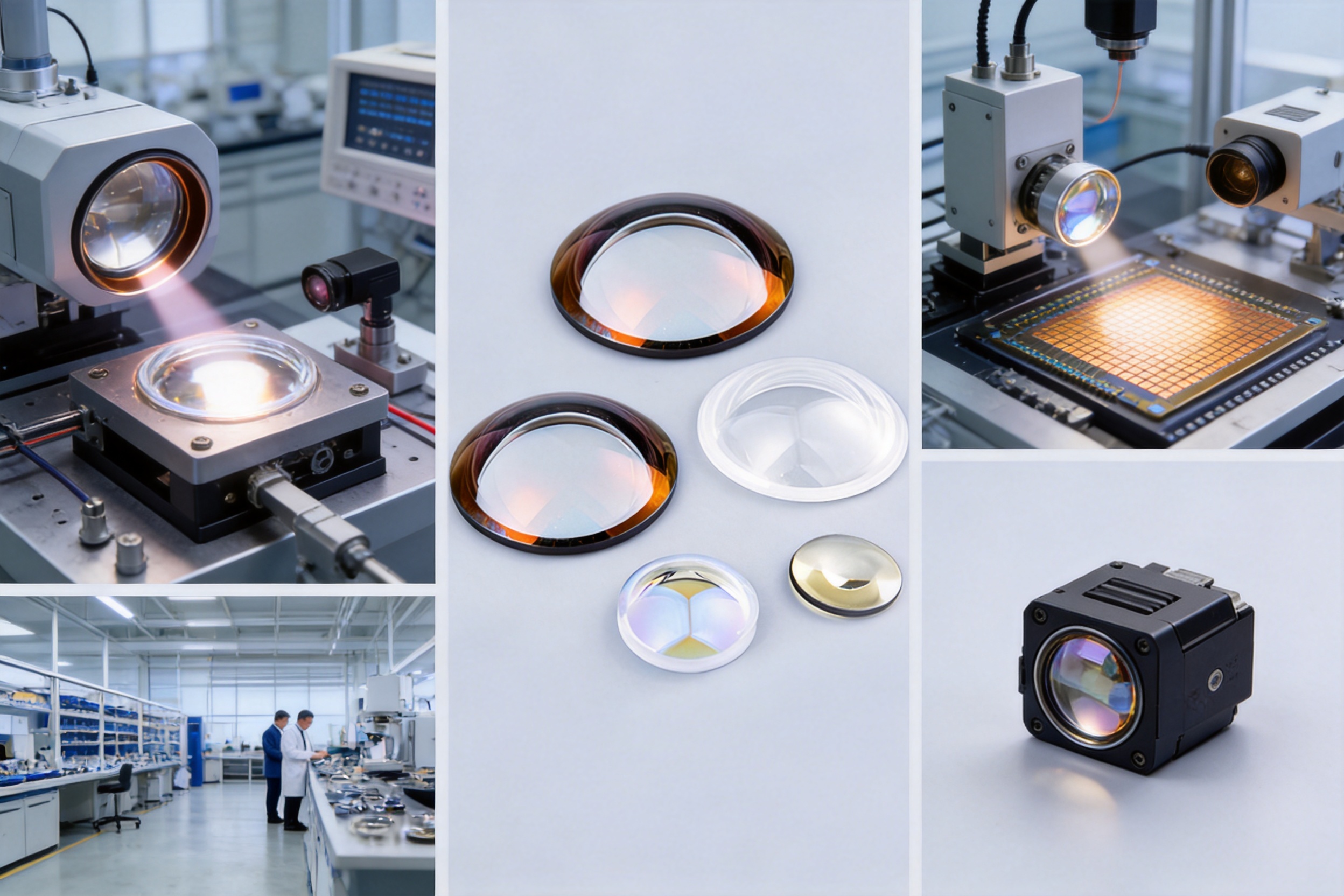
Optical spherical mirrors are precision reflective components designed to collect, redirect, focus, or expand light by means of a spherical surface. They are used in laser systems, imaging equipment, inspection instruments, automotive optical assemblies, semiconductor equipment, scientific devices, and many other applications in which controlled reflection is essential. Although the geometry is based on a section of a sphere, the manufacturing of a reliable optical spherical mirror requires much more than simply polishing a curved piece of glass. Substrate selection, radius control, surface accuracy, roughness, coating design, cleanliness, inspection, and packaging all influence the final performance of the component.
For equipment manufacturers and optical system designers, the most suitable mirror is not necessarily the lowest-priced product or the mirror with the highest nominal reflectivity. A successful component must provide a balanced combination of optical performance, dimensional consistency, environmental durability, production stability, and supply reliability. It must also be compatible with the wavelength, angle of incidence, aperture, mounting method, and operating environment of the complete optical system.
Changzhou Haolilai Photo-Electricity Scientific and Technical Co., Ltd., commonly known as HLL, is a professional manufacturer of precision optical components. Founded in 1998, the company develops and produces optical parts for laser optics, automotive optics, semiconductor optics, and consumer optics. Its product capabilities include optical spherical mirrors and other precision components such as optical lenses, prisms, flat mirrors, and specialized glass parts. With a production site covering approximately 35,000 square meters, an experienced technical team, and more than 300 employees, HLL serves customers in China and international markets.
This article explains the construction and working principles of optical spherical mirrors, their main advantages, the manufacturing processes that determine quality, and the reasons a specialized manufacturer can provide stronger performance than a general glass or metal-processing supplier. It also provides guidance for selecting, specifying, inspecting, and integrating spherical mirrors into optical equipment.
Understanding the Optical Spherical Mirror
An optical spherical mirror is a reflective optical component whose active surface follows a spherical profile. The surface may be concave or convex. A concave spherical mirror generally converges incident light toward a focal region, while a convex spherical mirror diverges reflected light and provides a wider field of view. Depending on the system design, the mirror can be used for focusing, beam redirection, image formation, beam expansion, or compact optical folding.
The basic geometry is defined by the radius of curvature. For a simple spherical mirror operating close to its optical axis, the approximate focal length is related to the radius of curvature by the familiar relationship:
f ≈ R/2
In this relationship, f is the approximate focal length and R is the radius of curvature. The equation is useful for preliminary design, but actual optical behavior also depends on aperture, wavelength, angle of incidence, surface accuracy, coating performance, and the position of the component in the system.
Spherical mirrors are often selected because they offer a practical balance between optical capability and manufacturing efficiency. Compared with more complex aspheric or freeform mirrors, a spherical surface can often be generated, polished, measured, and reproduced with established processes. This can make spherical mirrors attractive for high-volume products, cost-sensitive instruments, and systems in which the spherical aberration is acceptable or corrected elsewhere in the optical design.
The mirror normally consists of a substrate and a reflective coating. Common substrate materials include optical glass, fused silica, and other materials selected according to wavelength, thermal conditions, dimensional requirements, and cost. The reflective coating may be metallic, dielectric, or a multilayer design. The correct coating depends on the target spectral band, incidence angle, polarization requirements, environmental conditions, and desired reflectance.
Why Spherical Mirrors Remain Important in Modern Optical Systems
Optical designers have access to sophisticated aspheric, diffractive, and freeform components, but spherical mirrors continue to be important because they provide dependable performance with a well-understood manufacturing route. Their geometry is comparatively straightforward, which supports repeatable production and easier quality control. A spherical mirror can also be integrated into compact systems where a reflective path is more practical than a transmissive lens path.
Mirrors have an additional advantage in wavelength regions where transparent optical materials are expensive, difficult to manufacture, or limited in transmission. Because the light is reflected rather than transmitted through the substrate, the optical path can be designed around coating performance instead of bulk-material transmission alone. This is especially useful in laser and infrared-related applications, although the final suitability must always be verified for the intended wavelength.
Reflective components can also reduce chromatic effects compared with refractive elements. A well-designed mirror does not introduce chromatic dispersion in the same way as a lens because reflection occurs at the coated surface rather than through a substantial transmissive path. This feature can simplify certain broadband or multiwavelength optical designs.
In industrial equipment, another important benefit is layout flexibility. A spherical mirror can fold a beam, place a focus in a restricted space, or redirect light around mechanical obstacles. In automotive optical modules, it may support compact imaging or illumination architectures. In semiconductor inspection equipment, it may be used where stable alignment and controlled surface quality are needed in a small optical envelope.
Key Performance Characteristics
Radius of Curvature
The radius of curvature determines the fundamental focusing or diverging behavior of the mirror. Tight radius requirements demand suitable generating, grinding, and polishing methods, as well as accurate measurement. A small deviation from the intended radius can shift the focal position and affect the performance of the complete system.
For production orders, the radius should be defined together with its tolerance, measurement method, reference wavelength if relevant, and the area over which the radius is evaluated. The customer and manufacturer should also clarify whether the requirement concerns the best-fit sphere, the vertex radius, or a specified clear aperture.
Surface Figure
Surface figure describes how closely the actual optical surface follows the intended spherical shape. Figure errors can create wavefront distortion, reduce image quality, broaden a laser focus, or introduce unwanted beam deviation. The acceptable figure tolerance depends on the application. A basic illumination mirror may not require the same precision as a mirror used in high-resolution imaging or a tightly focused laser assembly.
A professional manufacturer controls surface figure through stable tooling, controlled polishing pressure, suitable slurry management, repeated measurement, and process feedback. The objective is not merely to achieve a good result on one component, but to maintain a consistent result across a complete production batch.
Surface Roughness
Surface roughness affects scatter. Even when the overall spherical figure is correct, microscopic irregularities can reduce usable optical power and create stray light. Lower roughness is generally important for laser optics, imaging systems, and instruments with sensitive detectors.
Roughness is influenced by substrate quality, abrasive selection, polishing chemistry, pad condition, cleaning, and the final finishing stage. It should be evaluated with an appropriate instrument and reported according to a defined measurement convention.
Clear Aperture
The clear aperture is the portion of the mirror that meets the required optical specifications. It is not always identical to the physical diameter because an edge exclusion zone may be required for handling, mounting, or coating protection. Designers should specify the clear aperture, edge condition, and any usable-area restrictions so that the component performs as intended after installation.
Reflectance
Reflectance is determined primarily by the coating system and the angle of incidence. A mirror optimized for visible light may not be suitable for near-infrared or ultraviolet operation. Similarly, a coating designed for near-normal incidence may not provide the same performance at a large incident angle.
When specifying a coating, the customer should identify the central or working wavelength, operating bandwidth, angle of incidence, polarization sensitivity, power level, and environmental exposure. For laser use, damage threshold and coating absorption may be critical. For imaging or illumination, broadband behavior and color balance may be more important.
Back Surface and Edge Quality
The back surface may be flat, ground, polished, or otherwise prepared according to the mounting design. Although it is not normally part of the active optical path, it can affect seating, alignment, thermal contact, and mechanical stability. Edge chips, sharp edges, and coating defects can create handling risks or interfere with installation. Proper edge treatment and inspection are therefore important parts of product quality.
Advantages of Precision Optical Spherical Mirrors
Efficient Use of Optical Space
A spherical mirror can provide focusing or beam redirection without requiring a long transmissive optical path. This enables compact layouts in instruments where space is limited. The mirror can be placed at a strategic angle or position to fold the beam and reduce the overall system length.
Reduced Chromatic Dispersion
Reflective systems can reduce chromatic effects that would otherwise arise in transmissive elements. This is advantageous for broadband imaging, multiwavelength inspection, and systems that must maintain similar geometry across more than one spectral band. Coating selection remains important, but the mirror architecture can simplify chromatic management.
Flexible Wavelength Configuration
By changing the coating design, a spherical mirror can be adapted to different spectral applications. Metallic coatings may support broad spectral coverage, while dielectric multilayers can provide high reflectance within a defined wavelength range. The substrate and coating must be selected together because thermal expansion, adhesion, absorption, and environmental stability influence long-term performance.
Repeatable Geometry
The spherical form is suitable for established optical manufacturing methods. This supports repeatability and makes it easier to scale from prototype quantities to production volumes. A repeatable radius and surface figure help reduce alignment variation between instruments and lower the need for individual optical compensation.
Potential Cost Advantage
Compared with more complex freeform or high-order aspheric surfaces, spherical mirrors can provide a favorable cost-to-performance ratio. Their advantage is strongest when the optical system can tolerate the remaining spherical aberration or when other elements are used to compensate for it. The total cost should be evaluated across manufacturing, inspection, assembly, adjustment, and field service rather than by unit price alone.
Compatibility with Compact and Industrial Equipment
Optical spherical mirrors can be supplied in various sizes, thicknesses, apertures, and mounting configurations. They can be used in instruments that require compact reflective paths, robust alignment, or repeatable optical output. This makes them suitable for laboratory equipment as well as industrial machines operating continuously in controlled environments.
Why Manufacturer Capability Matters
The difference between a basic reflective part and a precision optical spherical mirror is the control of the entire process chain. A supplier may be able to produce a curved glass surface, but that does not automatically mean the component will have the required figure, roughness, coating uniformity, cleanliness, and batch consistency.
A specialized manufacturer brings together optical design understanding, glass processing, precision polishing, coating technology, metrology, quality management, and production engineering. These disciplines must work together. For example, an excellent polished surface can still fail if the coating introduces defects, if cleaning leaves particles, or if packaging allows abrasion during transportation.
HLL has operated in the precision optical component field since 1998. Its experience covers several application sectors, including laser optics, automotive optics, semiconductor optics, and consumer optics. This broad application background helps the company understand that the right optical component must be evaluated in the context of a complete system rather than as an isolated glass part.
The company reports certifications including ISO9001:2015, ISO14001:2015, and IATF16949. These certifications represent structured approaches to quality management, environmental management, and automotive quality requirements. Certification alone does not replace product-specific technical verification, but it indicates that documented systems, process control, corrective action, and traceability are treated as important operational responsibilities.
HLL also has an experienced technical team and has established the Jiangsu Precision Optical Lens Engineering Technology Center and the Jiangsu Enterprise Technology Research Center. These technical resources support product development, process improvement, and the translation of customer requirements into manufacturable optical designs.
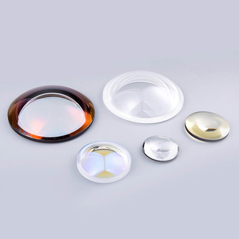
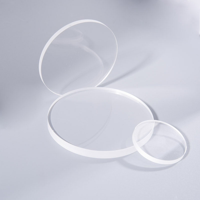
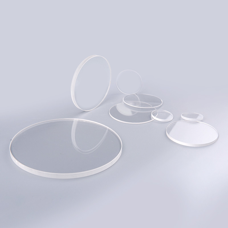
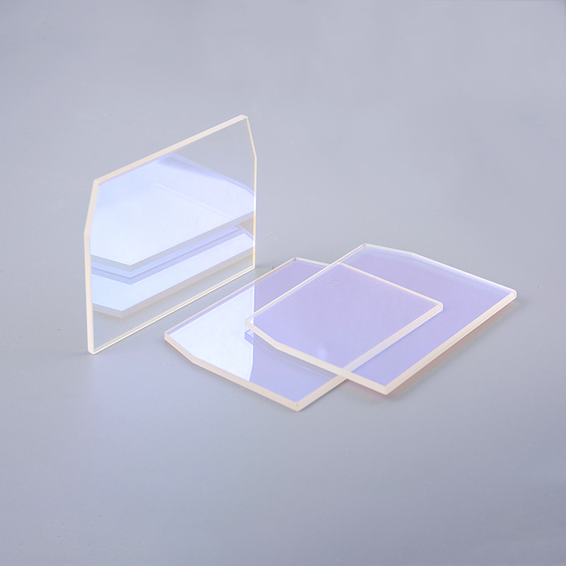
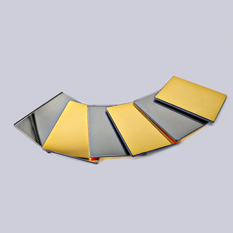
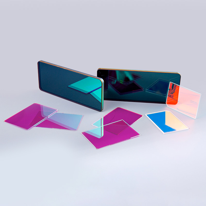
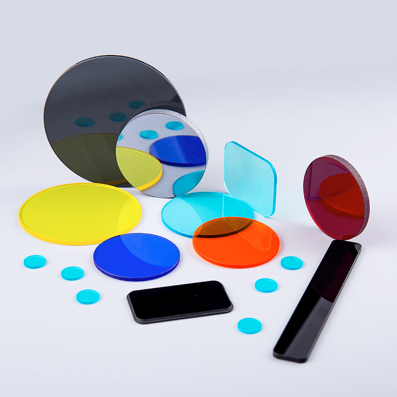
Optical Spherical Mirror
Advanced Manufacturing Process for Optical Spherical Mirrors
1. Requirement Review and Optical Engineering
Manufacturing begins with a technical review of the product requirements. The manufacturer evaluates the drawing, three-dimensional data, optical prescription, coating needs, tolerance stack, inspection requirements, packaging conditions, and intended application. Any ambiguity in the drawing should be clarified before production begins.
Important questions include whether the mirror is concave or convex, the target radius of curvature, the required clear aperture, the operating wavelength, the angle of incidence, the allowable surface figure, the roughness limit, the coating type, and the mechanical interface. It is also useful to define whether the mirror will be bonded, clamped, mounted in a cell, or integrated into a larger optical module.
A detailed design review can prevent costly late-stage changes. For example, a coating requirement may affect the permissible substrate material, while a narrow edge zone may affect the polishing fixture. A tight radius tolerance may require additional measurement and process time. Early coordination allows the manufacturer to select an efficient and stable route.
2. Substrate Selection
The substrate provides the mechanical and thermal foundation of the mirror. Optical glass is often selected for general-purpose precision optics because of its availability, processability, and dimensional stability. Fused silica may be considered where low thermal expansion, ultraviolet transmission properties, or high thermal stability are important. Other substrate choices may be appropriate for specialized wavelength or environmental requirements.
Substrate selection considers homogeneity, internal stress, inclusions, bubbles, striae, thermal expansion, hardness, density, and compatibility with the coating process. A substrate with unsuitable internal quality can limit final performance even if the external surface is polished to a high standard.
3. Blanking and Preform Preparation
The raw material is cut or formed into a preform with allowance for grinding and polishing. The preform must have enough material to reach the final geometry while avoiding excessive removal. Dimensional allowances are planned according to the component size, curvature, edge condition, and expected process behavior.
At this stage, orientation, marking, and traceability are important. Components should be identified in a way that supports process tracking without damaging the optical surface. Proper handling reduces the risk of scratches, chips, contamination, and mix-ups between different product specifications.
4. Curve Generation
Curve generation establishes the basic spherical form. Controlled grinding removes material and brings the workpiece close to the target radius. The process must manage tool geometry, abrasive size, pressure, speed, coolant, and workpiece support.
The generated surface is not yet suitable for optical use, but it establishes the foundation for later polishing. If the initial curvature is uneven or excessively stressed, later stages may require additional correction. Stable fixtures and suitable tooling help maintain the intended shape across the complete aperture.
5. Fine Grinding
Fine grinding removes the deeper damage created during rough generation and improves the consistency of the surface. Abrasive size is gradually reduced, and the workpiece is cleaned between stages to prevent coarse particles from being carried into a finer process.
Fine grinding is a critical transition stage. Insufficient removal of subsurface damage can lead to extended polishing time or hidden defects. Excessive grinding can reduce dimensional efficiency and make it more difficult to maintain the intended radius. Controlled process records help ensure that each stage contributes to the final result.
6. Precision Polishing
Polishing transforms the fine-ground surface into an optically smooth reflective surface. The polishing tool, pad, slurry, pressure, speed, and dwell pattern are selected according to the mirror geometry and material. The process must remove microscopic damage while preserving the spherical figure.
Polishing a curved mirror requires careful management of edge behavior and aperture uniformity. If the edge is over-polished or under-polished, the effective clear aperture may be reduced. If the process is not balanced, the surface can develop zones, irregularity, or unwanted departure from the best-fit sphere.
Modern production methods combine experienced process engineering with measurement feedback. The component is measured, deviations are analyzed, and the polishing process is adjusted when necessary. This closed-loop approach is more reliable than depending solely on fixed polishing time.
7. Cleaning and Surface Preparation
After polishing, the mirror must be thoroughly cleaned. Residual slurry, particles, oils, and handling contamination can compromise coating adhesion or create visible defects. Cleaning procedures are selected according to the substrate, polishing chemistry, coating system, and cleanliness standard.
Clean handling is especially important for laser and semiconductor-related optics. A particle that appears insignificant during visual inspection may become a source of scattering, absorption, or localized damage when exposed to a concentrated laser beam. Controlled cleaning, drying, inspection, and packaging reduce these risks.
8. Coating Deposition
The coating is applied in a controlled vacuum environment or by another qualified deposition method suited to the required performance. Metallic coatings may be selected for broad spectral response, while dielectric multilayers can be engineered for high reflectance in a specified band. Protective overcoats may be added when environmental durability is required.
Coating design must account for wavelength, incidence angle, polarization, power density, substrate temperature, adhesion, abrasion resistance, and humidity exposure. Uniformity across the clear aperture is essential because variations in thickness can produce reflectance differences or spectral shifts.
For production consistency, the coating chamber, fixtures, cleaning sequence, deposition parameters, and monitoring equipment must be controlled. Witness samples or process monitors may be used to verify coating performance without sacrificing every production component to destructive testing.
9. Final Inspection
Final inspection may include dimensional measurement, radius verification, surface figure testing, roughness evaluation, visual inspection, coating reflectance measurement, adhesion testing, environmental testing, and cleanliness checks. The exact inspection plan should match the drawing and application risk.
Optical testing methods can include interferometric measurement, profilometry, coordinate measurement, spectrophotometric evaluation, and visual inspection under controlled illumination. No single test describes every aspect of performance. A mirror can pass a radius check but fail a coating uniformity requirement, or show good reflectance while having unacceptable edge damage.
10. Protective Packaging and Traceability
Precision mirrors require packaging that prevents contact, abrasion, particle generation, and moisture-related problems. Individual protection, suitable cushioning, clean bags, protective caps, and stable outer packaging may be used depending on the product and shipping conditions.
Traceability records connect the finished component to its substrate batch, processing route, coating lot, inspection results, and packing information. This is valuable for incoming inspection, production troubleshooting, repeat orders, and long-term quality improvement.
Competitive Advantages of a Specialized Supplier
Integrated Optical Component Expertise
A supplier focused on optical components is more likely to understand the relationship between geometry, surface quality, coating, and system performance. This is a significant advantage over a general machining company that treats the mirror as a simple curved part. Integrated optical expertise allows technical recommendations to be made before the product reaches production.
Experience Across Multiple Markets
HLL serves several demanding optical sectors. Laser optics require careful control of surface defects, absorption, and coating performance. Automotive optics require repeatability, durability, and compatibility with strict industrial quality processes. Semiconductor optics require cleanliness, dimensional precision, and stable supply. Consumer optics often require efficient production and consistent appearance at competitive cost.
Experience across these sectors can strengthen manufacturing discipline because lessons from one application may improve process control in another. The final product still needs to be qualified against its own specification, but broad experience supports better problem solving and production planning.
Quality and Environmental Management
ISO9001:2015 certification reflects a structured quality management framework, while ISO14001:2015 addresses environmental management practices. IATF16949 is associated with automotive quality management expectations and process discipline. For customers purchasing optical spherical mirrors for industrial or automotive programs, these systems can provide greater confidence in documented procedures, change control, corrective action, and supplier coordination.
Technical Research Infrastructure
The Jiangsu Precision Optical Lens Engineering Technology Center and Jiangsu Enterprise Technology Research Center provide a platform for engineering development and technical improvement. Research capability is particularly valuable when a customer requires a new radius, unusual dimension, special coating, higher cleanliness level, or improved production yield.
Production Scale and International Experience
With more than 300 employees and exports to more than 20 countries, HLL has experience supporting customers with different communication practices, documentation expectations, packaging requirements, and delivery arrangements. A manufacturer with international order experience is generally more prepared to manage drawings, samples, inspection reports, production batches, and repeat-order consistency.
The company reports more than 30 certificates and patents, including invention patents, utility model patents, and Jiangsu High and New Tech Products. These achievements indicate ongoing investment in technology and process development. Customers should still review the specific technical data for each mirror, but the company’s development background is a useful indicator when evaluating long-term cooperation.
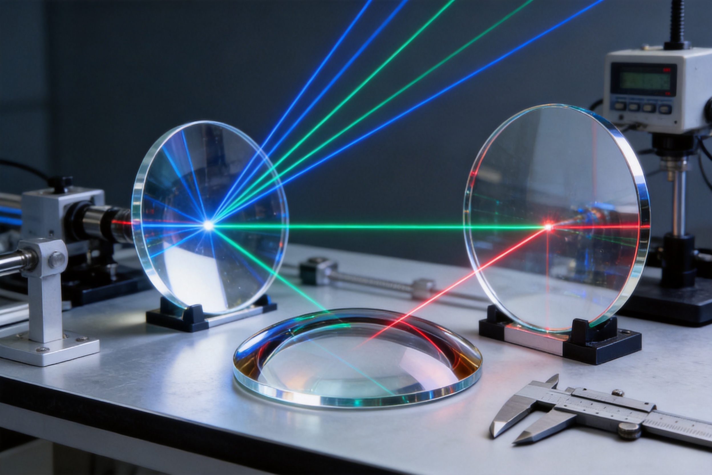
Comparison with Alternative Mirror Types
| Mirror type | Primary geometric feature | Typical strength | Important consideration |
|---|---|---|---|
| Concave spherical mirror | Concave spherical reflecting surface | Focusing, beam collection, compact optical folding | May produce spherical aberration at larger apertures or off-axis use |
| Convex spherical mirror | Convex spherical reflecting surface | Beam divergence and expanded field of view | Requires careful control of distortion and mounting alignment |
| Optical flat mirror | Plane reflecting surface | Beam redirection without intentional focusing | Does not provide the focusing behavior of a curved mirror |
| Parabolic mirror | Parabolic reflecting surface | Reduced on-axis spherical aberration and collimation performance | More complex geometry and often higher manufacturing cost |
| Elliptical mirror | Ellipsoidal reflecting surface | Imaging or transferring light between two focal points | Requires precise control of multiple geometric parameters |
| Freeform mirror | Non-rotationally symmetric surface | Advanced correction and specialized optical layouts | More demanding design, measurement, and production process |
The spherical mirror is not universally superior to every alternative. Its advantage lies in the balance it offers. When a system can accommodate spherical behavior, the component may provide a more economical, repeatable, and accessible solution than a parabolic or freeform mirror. When spherical aberration cannot be tolerated, a different geometry or a combination of corrective elements may be necessary.
A competent supplier should help customers make this decision based on the optical prescription rather than pushing one product type for every application. In some cases, a spherical mirror may be the best choice. In other cases, the manufacturer may recommend a flat mirror, aspheric component, prism, or customized optical assembly.
Applications of Optical Spherical Mirrors
Laser Systems
Concave spherical mirrors can focus or collect laser energy, while convex designs can help expand or redirect beams. They may be used in optical paths, resonator-related assemblies, beam conditioning modules, scanning equipment, and industrial processing systems.
Laser applications require special attention to coating absorption, laser-induced damage threshold, surface scatter, contamination, and thermal effects. The mirror must be specified for the exact wavelength and power conditions. A coating with high reflectance at a low-power test wavelength may not be suitable for a high-power continuous-wave or pulsed laser.
Semiconductor Inspection and Metrology
Inspection equipment often requires stable and repeatable optical behavior. Spherical mirrors can help create compact paths, direct illumination, collect reflected signals, or support imaging architectures. Surface cleanliness and low scatter may be particularly important because unwanted reflections can reduce contrast or obscure small defects.
Dimensional stability and reliable traceability are also valuable in semiconductor equipment. A small change in radius or mounting position can influence calibration, so production consistency and clear inspection records support equipment maintenance and repeatability.
Automotive Optical Systems
Automotive optical modules may use reflective components in imaging, sensing, illumination, display, or interior optical systems. The component must often meet strict dimensional, appearance, durability, and batch-consistency requirements. The operating environment may include temperature variation, vibration, humidity, and long service periods.
For automotive programs, IATF16949-related quality processes can be an important supplier consideration. The optical mirror must be evaluated not only for laboratory performance but also for its ability to remain stable through assembly, transportation, environmental exposure, and vehicle operation.
Scientific and Laboratory Instruments
Laboratory systems benefit from the availability of well-characterized optical components. Spherical mirrors can be used in spectroscopic instruments, imaging devices, optical experiments, beam transport systems, and compact research equipment. Their predictable geometry makes them convenient for system designers who need a practical component with defined optical behavior.
Consumer and Imaging Equipment
Compact imaging and sensing products often require small optical components that can be produced consistently at controlled cost. Spherical mirrors may support folded optical layouts, illumination management, or image path redirection. Appearance quality and contamination control can be important when the mirror is installed near visible surfaces or sensitive detectors.
How to Specify an Optical Spherical Mirror
A clear specification reduces quotation time, prevents misunderstandings, and improves the probability of first-article approval. The drawing or technical document should include the following information wherever applicable.
First, identify the mirror type as concave or convex and define the nominal radius of curvature. Include the radius tolerance and the measurement reference if the requirement is particularly tight.
Second, specify the outside diameter or length and width, center thickness, edge thickness, and allowable dimensional tolerances. If the part is mounted in a cell, include the actual interface dimensions and clearance requirements.
Third, define the clear aperture and any edge exclusion. The optical specification should apply to the area that will actually be used by the system.
Fourth, state the surface figure and roughness requirements. Terms such as peak-to-valley, root mean square, or a best-fit-sphere deviation should be used clearly and consistently. If a particular test method is required, it should be identified in the purchase documentation.
Fifth, provide the wavelength range and coating requirement. Include the expected angle of incidence, polarization condition if relevant, reflectance target, environmental durability, and laser power information.
Sixth, describe cosmetic requirements, including allowable scratches, digs, stains, pinholes, coating marks, edge chips, and handling defects. Cosmetic standards may vary significantly between visible imaging, laser, automotive, and industrial products.
Seventh, define inspection documents and packaging requirements. Depending on the application, customers may request a certificate of conformity, dimensional report, coating report, material certificate, environmental test result, or batch traceability record.
Inspection and Quality Assurance Considerations
Incoming inspection should be based on the risk profile of the component. Visual inspection can identify obvious scratches, chips, coating marks, and contamination, but it cannot replace quantitative measurement of radius, figure, roughness, or reflectance.
For a production program, it is useful to agree on sampling plans and acceptance criteria before the first batch. Measurement instruments should be calibrated, and the test method should be stable enough to compare results between the supplier and customer. Differences in aperture definition, test setup, reference sphere, or data processing can otherwise create disagreements even when the physical components are similar.
First-article approval is an effective way to confirm that the drawing, manufacturing route, coating, packaging, and inspection method are aligned. After approval, any material, coating, tooling, or process change should be managed through a defined change-control procedure, especially for automotive and semiconductor applications.
Quality assurance also includes process capability. A supplier should not rely only on final sorting to achieve consistency. Stable incoming materials, controlled polishing, preventive equipment maintenance, operator training, in-process measurement, and documented corrective actions are more effective ways to reduce variation.
Common Causes of Optical Mirror Failure
Incorrect Coating Selection
A coating optimized for one wavelength may perform poorly at another. Large-angle incidence can also shift the spectral response. The coating must be selected using actual operating conditions rather than a general label such as “high-reflectance mirror.”
Insufficient Surface Quality
Deep scratches, pits, haze, or high roughness can increase scatter and reduce image or laser performance. The defect standard should be appropriate to the application and verified over the required clear aperture.
Radius or Figure Deviation
An incorrect radius can shift the focal point, while figure errors can distort the wavefront. These problems may be difficult to correct after assembly, so they should be controlled during manufacturing rather than discovered only during final system testing.
Contamination
Particles, fingerprints, residues, and packaging debris can cause scatter, reduce reflectance, or create damage under laser illumination. Clean handling and suitable packaging are essential from final inspection through assembly.
Mechanical Stress
Excessive clamping force, uneven bonding, or poor seating can deform the mirror after it has passed optical inspection. The mounting method should be reviewed together with the mirror design. A high-quality component can still perform poorly if the mechanical interface introduces stress.
Thermal Mismatch
Temperature changes can affect the substrate, coating, adhesive, mount, and surrounding structure differently. For precision systems, the thermal expansion behavior of the complete assembly should be considered during design and validation.
Design Recommendations for Better System Performance
Use the smallest practical aperture that meets the beam or imaging requirement, while retaining sufficient margin for alignment and manufacturing tolerances. An unnecessarily large aperture can increase cost and make figure control more difficult.
Keep the angle of incidence within a range appropriate for the selected coating and system geometry. If the mirror is used far off axis, evaluate polarization effects, footprint changes, and effective aperture.
Allow for mounting tolerances in the optical design. The nominal radius alone does not guarantee the final focal location if the mirror is tilted, decentered, or stressed during assembly.
Define the working wavelength and power level at the beginning of the supplier discussion. Coating design is not an afterthought. It is one of the central performance characteristics of the mirror.
Specify cleanliness and packaging according to the final assembly environment. A mirror for a general laboratory instrument may need a different cleanliness and packing process from a mirror for a semiconductor inspection tool.
Request sample evaluation before committing to large-scale production when the application is new or unusually demanding. Prototype testing can reveal mounting sensitivity, coating behavior, scatter, thermal effects, and integration issues that are not obvious from a drawing alone.
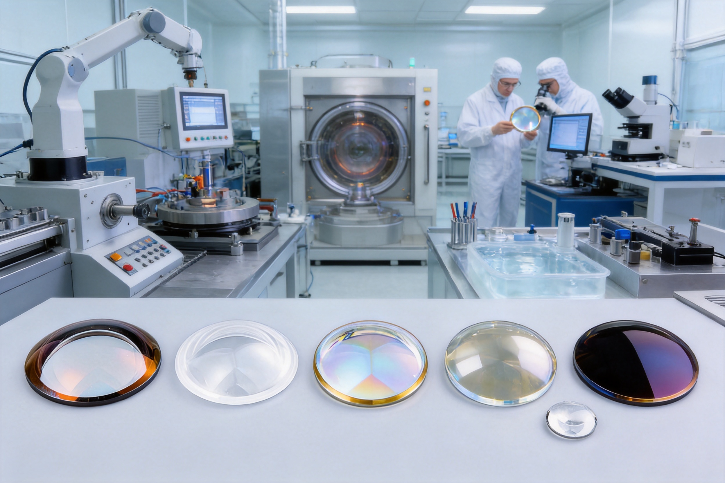
Production Partnership with Changzhou Haolilai Photo-Electricity Scientific and Technical Co., Ltd.
HLL offers a manufacturing background focused on precision optical components rather than general-purpose glass products. The company was established in 1998 and has developed its business around the production and improvement of optical parts for multiple technical markets. Its stated product focus includes laser optics, automotive optics, semiconductor optics, and consumer optics.
The company’s 35,000-square-meter site provides a substantial operational base for manufacturing, engineering, inspection, and supporting activities. Its workforce of more than 300 employees offers the personnel capacity needed to coordinate technical development, production planning, quality management, and customer service.
HLL’s technical development structure includes the Jiangsu Precision Optical Lens Engineering Technology Center and Jiangsu Enterprise Technology Research Center. These centers support engineering work and process development, which can be valuable when customers require customized dimensions, non-standard radii, coating adjustments, or improved production efficiency.
The company has obtained invention patents, utility model patents, and Jiangsu High and New Tech Products. Its reported certifications include ISO9001:2015, ISO14001:2015, and IATF16949. Together with international export experience to more than 20 countries, these qualifications support its position as a potential long-term supplier for customers requiring repeatable optical spherical mirrors.
Customers evaluating a supplier should still conduct a product-specific assessment. The most useful evaluation includes drawing review, sample inspection, coating verification, quality-document review, packaging assessment, and a discussion of production capacity. The supplier’s general capability is important, but the final decision should be based on evidence that the selected mirror meets the actual application requirements.
Frequently Asked Questions
What is an optical spherical mirror?
An optical spherical mirror is a reflective component with a concave or convex surface shaped as part of a sphere. It is used to focus, diverge, redirect, collect, or form images from reflected light.
What is the difference between a concave and a convex spherical mirror?
A concave spherical mirror curves inward and generally converges incident light toward a focal region. A convex spherical mirror curves outward and generally diverges reflected light, producing a wider field of view or an expanded beam path.
Are spherical mirrors suitable for laser applications?
They can be suitable for laser applications when the substrate, surface quality, coating, wavelength, angle of incidence, power level, and damage-threshold requirements are properly matched. A general-purpose mirror should not be assumed to be suitable for high-power laser use.
How does a spherical mirror compare with a parabolic mirror?
A spherical mirror is generally easier to manufacture and can offer a favorable cost and repeatability balance. A parabolic mirror can reduce certain forms of spherical aberration and may be preferred for demanding collimation or focusing tasks. The appropriate choice depends on aperture, beam geometry, field angle, performance targets, and budget.
Does a spherical mirror have chromatic aberration?
Reflection does not produce chromatic dispersion in the same manner as a conventional transmissive lens. However, coating reflectance can vary with wavelength, and the overall optical system may still have wavelength-dependent behavior. Broadband performance should therefore be verified for the intended spectral range.
What materials can be used for the substrate?
Optical glass and fused silica are common choices, but the best material depends on wavelength, thermal conditions, dimensional stability, hardness, cost, and coating compatibility. The substrate should be selected as part of the complete optical and manufacturing design.
What coating should be selected?
The coating should be selected according to wavelength, bandwidth, incidence angle, polarization, reflectance, laser power, and environmental exposure. Metallic coatings may provide broad response, while dielectric multilayers may provide high reflectance over a defined band.
Why are surface figure and roughness both important?
Surface figure controls how accurately the mirror follows its intended spherical shape and therefore affects wavefront and imaging behavior. Roughness describes microscopic texture and mainly influences scatter. A mirror must control both characteristics to provide reliable optical performance.
Can optical spherical mirrors be customized?
Yes. Customization may include radius, diameter, thickness, clear aperture, edge treatment, substrate material, coating, mechanical features, inspection criteria, and packaging. The feasibility of each requirement should be confirmed through a technical review.
What should be included in a purchase drawing?
The drawing should include geometry, radius and dimensional tolerances, clear aperture, surface figure, roughness, coating specification, wavelength, angle of incidence where relevant, cosmetic standards, edge condition, inspection requirements, and packaging instructions.
How can customers verify supplier quality?
Customers can review certifications, technical records, sample data, inspection methods, process controls, coating results, traceability, corrective-action procedures, and packaging performance. A first-article inspection is recommended for new or critical applications.
Why choose an experienced optical component manufacturer?
An experienced optical manufacturer understands the complete process from substrate preparation and curvature generation to polishing, coating, inspection, and packaging. This integrated knowledge helps reduce variation, prevent defects, improve manufacturability, and support repeat orders.
Conclusion
Optical spherical mirrors remain a practical and valuable solution for focusing, beam control, imaging, and compact reflective optical layouts. Their spherical geometry supports established manufacturing methods, repeatable production, and a favorable balance between performance and cost. With the correct substrate, surface quality, coating, and mounting design, they can serve demanding applications in laser systems, semiconductor equipment, automotive optics, scientific instruments, and consumer products.
The most important advantages of a high-quality spherical mirror are not limited to nominal reflectance or appearance. Radius accuracy, surface figure, low roughness, coating uniformity, dimensional consistency, environmental durability, cleanliness, and traceability all contribute to the final result. These characteristics depend on a controlled manufacturing chain and a supplier capable of coordinating optical engineering with production and quality assurance.
Changzhou Haolilai Photo-Electricity Scientific and Technical Co., Ltd. brings experience dating from 1998, a substantial manufacturing site, more than 300 employees, international export experience, technical research centers, multiple patents, and certifications including ISO9001:2015, ISO14001:2015, and IATF16949. Its focus on laser, automotive, semiconductor, and consumer optics provides a foundation for developing and manufacturing precision optical spherical mirrors according to application-specific requirements.
For customers selecting a supplier, the best approach is to define the optical and mechanical requirements clearly, confirm the coating and inspection method, evaluate representative samples, and establish a documented process for quality control and change management. When these steps are followed, an optical spherical mirror can provide stable performance, efficient integration, and dependable service over the life of the optical system.
References
1. Eugene Hecht, Optics, principles of geometrical optics, reflection, imaging, and optical aberrations.
2. Warren J. Smith, Modern Optical Engineering, optical system design, tolerances, mirrors, and manufacturing considerations.
3. Daniel Malacara, Optical Shop Testing, methods for evaluating optical surfaces, figure accuracy, and interferometric performance.
4. International Organization for Standardization, ISO 9001:2015, Quality Management Systems—Requirements.
5. International Organization for Standardization, ISO 14001:2015, Environmental Management Systems—Requirements with Guidance for Use.
6. International Automotive Task Force, IATF 16949, Quality Management System Requirements for Automotive Production and Relevant Service Parts Organizations.
7. Optical Society and professional optical engineering literature concerning reflective coatings, surface scatter, optical substrates, and laser-induced damage.
8. Technical and company information supplied for Changzhou Haolilai Photo-Electricity Scientific and Technical Co., Ltd., including company history, product focus, certifications, research centers, patents, production scale, and international market experience.


 苏公网安备32041102000130号